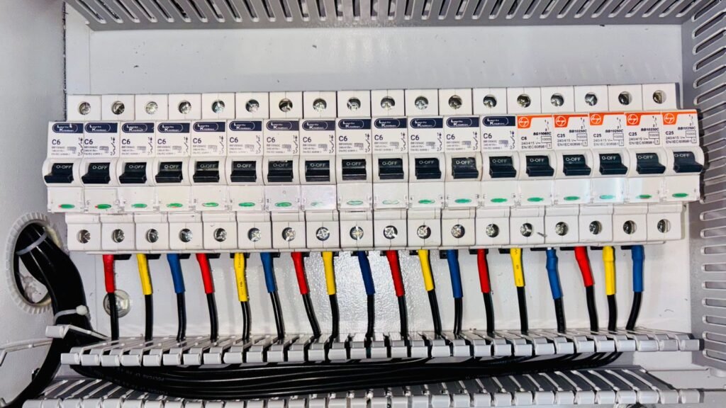

Titania status LED diagnostics give a commissioning engineer a fast way to separate four different questions at the cabinet: is the module operating, is RS-485 traffic reaching it, are field inputs being detected, and are output channels being commanded? Titania provides SYS, COM, DI1–DI8 and DO1–DO8 front-panel indication, backed by Modbus status and diagnostic data. The useful result comes from comparing those observations, not from treating any single lamp as a complete diagnosis.
Titania status LED diagnostics divide the signal path into four observations
A remote-I/O fault can sit in the field device, field wiring, input configuration, network, PLC logic, output circuit or load. Looking at the entire chain at once makes troubleshooting slow. Titania’s indicator groups let the engineer split that chain into manageable sections:
- SYS provides local system indication.
- COM provides local communications indication.
- DI1–DI8 show the state of the eight digital-input channels.
- DO1–DO8 show the state of the eight digital-output channels.
The controlled datasheet states that these indicators complement Modbus status, counter, frequency and supported output-fault information. It does not define universal colour or blink meanings, so the released hardware and firmware documentation for the delivered unit remains the authority for those details.
Begin with SYS before chasing field wiring
Start by checking the 24 VDC supply, polarity, branch protection and terminal references against the released wiring drawing. Titania’s specified operating range is 19.2 to 28.8 VDC. If the SYS indication is absent or differs from the documented state, pause the I/O investigation and confirm the module supply at the terminals with an appropriate meter.
This first step prevents a common commissioning mistake: spending time on sensors or Modbus settings when the controller itself is not in a valid operating condition. A visible SYS indication is useful evidence, but it is not a substitute for measuring supply voltage or checking the delivered-revision documentation.
Use COM with a known Modbus transaction
A COM indication becomes most useful when the master sends a deliberate, repeatable poll to Titania. Use the configured slave address, baud selection, serial format and response delay, then observe whether local communications indication changes while the master records requests, responses and errors.
If the master times out and there is no corresponding local communications activity, inspect the path before changing application logic: A/B polarity, two-wire daisy-chain topology, end termination, stub length, shield/common strategy and the selected device address. Titania supports slave addresses 1–247, automatic baud detection or fixed 9600, 19200, 38400 and 115200 bps, with 8E1, 8O1, 8N1 and 8N2 formats. A response delay of 0–50 ms is available for master timing and multidrop compatibility.
If local activity is present but the master still rejects the exchange, compare serial format, device address and timing at both ends. The detailed procedure is covered in the Titania Modbus RTU commissioning guide.
Compare each DI LED with the physical input and Modbus state
Titania’s eight inputs accept dry-contact, PNP and NPN field devices. During commissioning, exercise one input at a time and record three observations: the voltage or contact condition at the terminal, the corresponding DI indication, and the physical input state read through Modbus.
When all three agree, the complete acquisition path has been checked. When they do not, the mismatch narrows the search:
- A field signal with no DI indication points toward the selected input arrangement, common reference, polarity, wiring or filter configuration.
- A DI indication without the expected Modbus value points toward register selection, polling logic, stale data or a firmware/register-map mismatch.
- A changing Modbus state that never reaches the PLC application points beyond Titania, toward mapping, scaling, tags or control logic.
Input filtering matters during this test. A short pulse can be rejected by an intentional filter setting, while a bouncing contact can produce unstable state or counts when filtering is too short. Titania provides per-channel filtering, 32-bit counting and pulse-frequency measurement up to the stated input limit. Verify the applicable filter enumeration and timing against the released register map before changing it.
Separate output command, DO indication and load response
For an output channel, three conditions should be treated separately: what the master commands, what the channel indication shows, and what the connected load actually does. A commanded ON state is not proof that a valve, relay, lamp or siren has operated.
Commission outputs with the machine in a controlled state. Confirm the programmed power-up and communications-loss values first, then command one channel at a time. Compare the output coil, the DO indication, supported driver-fault status and a suitable electrical measurement at the load. Titania’s outputs are isolated high-side sourcing channels for 24 VDC loads, with current limiting and protection against short circuit, overvoltage and thermal conditions. Load current, inrush, inductive energy, enclosure temperature and simultaneous-channel loading still require engineering assessment.
Where a load does not respond, use the evidence to decide the next check. A missing command belongs in PLC or Modbus logic. A present command with supported fault status belongs in the output circuit or load investigation. A normal indication and voltage at the terminal with no mechanical action belongs downstream at the actuator. The Titania output fault diagnostics guide develops that distinction in more detail.
A practical panel-side sequence
Consider a packaging conveyor whose photoelectric sensor is visible at the field device but not at the PLC, while a reject solenoid also fails to operate. A disciplined sequence avoids changing several variables at once:
- Confirm the module supply and the documented SYS condition.
- Send a known Modbus poll and compare COM indication with the master log.
- Operate the sensor and compare terminal condition, DI channel indication and the relevant discrete-input value.
- Verify the PLC tag mapping before forcing any output.
- With the machine made safe, command the selected output and compare the coil value, DO indication, supported fault status and load-terminal measurement.
- Return all forced states to the approved operating configuration and record the result.
This approach identifies the boundary at which the expected signal stops. It also produces a useful commissioning record instead of a list of settings changed by trial and error.
What the indicator layer cannot prove
Front-panel indication is deliberately concise. It cannot by itself confirm RS-485 termination quality, cable shielding, sensor threshold margin, actuator current, inductive energy, mechanical motion or a safety function. It also cannot resolve a mismatch between the installed firmware and an outdated register map.
Titania’s local logic, sequencing, alarm and PWM profiles are control conveniences, not certified safety functions. Safety-related interlocks require a separately designed and validated safety system. Before design freeze or commissioning, retain the delivered hardware revision, firmware revision, terminal drawing and released Modbus register map with the project file.
Specify the evidence you need from remote I/O
Front-panel indicators are most effective when the commissioning plan defines what must be observed locally and what must be confirmed in the controller. Review the Tachyonic product range, use the product selector, or see the industrial automation solutions and engineering resources.
For a low-friction engineering review, send us the observed SYS/COM/DI/DO states, supply voltage, field-device or load type, wiring arrangement and Modbus settings. Contact Tachyonic Intelligence.
Featured image: “Technician Operating Industrial Equipment Control Panel” by Bulat843, sourced from Pexels under the Pexels licence. The image is illustrative and does not depict Titania hardware.