
Titania output fault diagnostics help an engineer answer a question that an output command alone cannot settle: did the field circuit actually behave as intended?
Titania provides eight isolated high-side sourcing outputs for 24 VDC loads. Each channel can be commanded over Modbus, but a commanded ON state is only one part of the picture. A disconnected load, loss of field supply, wiring fault, overload or thermal trip can all leave the control system with an output command that does not represent the real condition at the machine.
The practical approach is to commission the command, the supported driver-fault status and any available process feedback as separate signals. That produces more useful diagnostics without claiming that the I/O module can see conditions that require an external sensor.
Titania output fault diagnostics start with the load
The controlled Titania datasheet specifies eight isolated high-side sourcing outputs. The documented continuous rating is 0.7 A per channel with all eight channels active, subject to ambient temperature and thermal conditions. Short-duration surge and overload limiting are approximately 1.1 A.
Those figures are not a substitute for a load profile. A small contactor coil may draw a modest holding current but a much higher inrush. A solenoid can store enough energy to stress the driver repeatedly when switched off. Lamps, sirens and capacitive electronic loads can also behave very differently during the first few milliseconds after energisation.
Before connecting a load, record:
- normal operating current at the actual field voltage;
- measured or manufacturer-declared inrush current and duration;
- whether the load is inductive, resistive or capacitive;
- expected switching frequency and duty cycle;
- simultaneous loading across all eight channels;
- the highest expected enclosure temperature; and
- the external branch-protection arrangement.
Titania includes overcurrent, short-circuit, overvoltage and thermal protection in the output-driver design. It also provides output-fault information over Modbus where supported by the installed firmware and register map. The exact status bits, recovery behaviour and fault distinctions must be taken from the released register map for that firmware revision.
Command state and circuit health are different signals
A PLC usually knows what it asked the output to do. That does not prove current reached the load or that the mechanical device moved. A useful diagnostic model keeps three layers separate:
Output command
This is the requested ON or OFF state. It belongs to the control sequence and should be logged when troubleshooting intermittent operation.
Driver-fault status
This is the Titania status provided by the applicable firmware. It can indicate that the protected output stage has detected a condition requiring attention. Do not decode raw values using an old workbook or a register map from another firmware release.
External process feedback
This comes from the machine, not the output driver. A valve limit switch, contactor auxiliary contact, pressure switch or current sensor can confirm whether the commanded action occurred. Where the process needs positive confirmation, this feedback is what closes the diagnostic gap.
For example, a commanded valve output with no reported driver fault still does not prove that the valve opened. A broken wire downstream of the module, a failed coil or a stuck mechanism may require separate feedback to detect.
A practical PLC diagnostic pattern
The host program can combine the available signals into a small set of maintenance states. These are application-level states, not Titania fault codes:
- Off: no output command and no active fault indication.
- Commanded: output requested, with the process response still inside its allowed operating time.
- Confirmed: output requested and the external feedback agrees.
- Driver fault: Titania reports a supported output-fault condition.
- No process response: the command remains active, no driver fault is reported, but the external feedback does not arrive before the application timeout.
- Unexpected feedback: the process indicates an active state while the output command is OFF.
This separation makes alarm messages more useful. “DO3 fault reported” directs attention to the output stage and load circuit. “Valve did not open after DO3 command” points toward field wiring, the actuator, air or hydraulic supply, or the mechanical assembly. Combining both into a generic “output failed” alarm makes fault-finding slower.
Commissioning without damaging the output stage
Start with the field load disconnected and verify terminal identification, polarity, supply range and branch protection against the released wiring drawing. The Titania operating supply is specified as 19.2 to 28.8 VDC around a nominal 24 VDC system.
Connect a representative load using a protected or current-limited supply where practical. Command one channel at a time, confirm the terminal voltage under load and compare actual current with the engineering record. Then repeat with the expected combination of simultaneously active outputs while monitoring enclosure conditions.
Do not create a hard short simply to prove that protection exists. Fault testing should follow an approved production or commissioning procedure using controlled equipment and clearly defined limits. Protection features reduce the consequence of an abnormal condition; they are not an invitation to use an uncontrolled fault as a test method.
For inductive loads, the internal active clamp has a nominal 54 V characteristic in the controlled datasheet. Its energy capability is finite. Evaluate coil energy and switching frequency together, and use an external suppression device or interposing relay when the application exceeds the direct-drive envelope or requires different release behaviour.
Set the recovery policy before automatic operation
A machine should not recover from every output fault in the same way. A stack light may tolerate an automatic retry. A process valve or contactor may require the command to remain de-energised until an operator checks the circuit.
Define the policy in the PLC or supervisory controller around the firmware behaviour actually released for the unit. Typical design decisions include:
- whether the output command is removed immediately after a reported fault;
- whether one controlled retry is permitted;
- how long the channel must cool or remain de-energised;
- which faults require manual acknowledgement;
- what information is written to the event log; and
- how power-up and communications-loss states interact with the fault response.
Titania’s programmable startup and communications-loss states are separate from output diagnostics. Commission them together, but do not treat either function as a certified safety system. Safety-related isolation and interlocking require a separately designed and validated safety function.
Documentation that saves time later
For every output channel, keep the load type, nominal and inrush current, suppression method, branch-protection rating, normal switching duty and expected feedback signal in the panel documentation. Record the Titania hardware revision, firmware revision and matching Modbus register-map revision beside that information.
When a fault recurs, this record lets a technician compare the installed circuit with the design intent before replacing hardware. It also prevents a future firmware or register-map change from silently altering how the PLC interprets diagnostic data.
Review the Tachyonic product range, compare applications with the product selector, and see the related guidance on high-side outputs and inductive load protection and Titania safe-state commissioning. Additional application material is available in technical resources.
Working through a difficult 24 VDC load? Send the load type, nominal and inrush current, switching duty, enclosure temperature and required recovery behaviour for an engineering review.
Technical basis: Titania 8DI/8DO Industrial Super I/O datasheet TTN-DS-2026-001, Rev 08, issued 22 July 2026. Confirm the installed hardware, firmware and matching Modbus register map before commissioning.
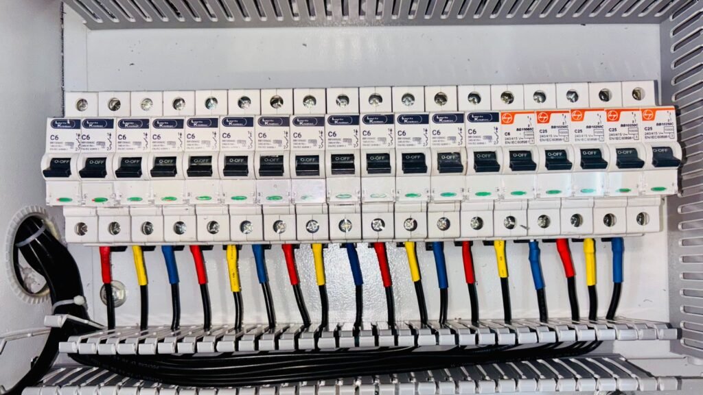
Featured image: electrical-panel diagnosis by Bulat843 via Pexels, used under the Pexels licence. The photograph illustrates field-circuit testing and does not depict Titania hardware.