
Titania sequencer commissioning should begin with a written output pattern, not with trial values in a register editor. Titania provides a local sequencing layer for its eight protected high-side outputs, with an active-channel mask, step interval, pulse width, loop pattern, sequence delay and one-shot or repeating control.
Those controls can remove repetitive output writes from a PLC for suitable local patterns. They also create a second source of output behaviour that must be documented and tested. The commissioning task is to prove which channels participate, how the pattern advances, how long each state remains active, and what the module does when a sequence is interrupted or restarted.
Titania sequencer commissioning starts with an output table
Write the intended pattern as a simple engineering table before configuring the module. Give every step a number, identify the outputs that should be energised, state the required dwell or pulse behaviour, and define what should happen after the last step. Include inactive channels explicitly. A blank cell can be misread later as “not used,” “off,” or “unchanged.”
The table should also name the real field loads. A channel labelled only as DO3 is difficult to review; a label such as “transfer chute solenoid” or “amber beacon segment” lets the electrical and controls teams check whether local sequencing is appropriate for the device.
Translate the table into the active-channel mask
The active-channel mask determines which outputs belong to the sequence. Confirm the channel order against the released register map and terminal drawing for the installed hardware and firmware revision. Do not infer bit order from a software display or copy a mask from another panel without checking the revision.
After writing the mask, read it back and test each selected output individually with the machine in a controlled condition. This catches swapped field wiring and reversed channel assumptions before automatic movement begins. Outputs not included in the mask should also be observed during the entire test; their state must not change as a side effect of the sequence.
Choose linear or pendulum movement deliberately
Titania supports linear and pendulum loop patterns. A linear pattern progresses through the selected channels and then returns to the beginning. A pendulum pattern reverses direction at the end of the run. That difference changes the transition at both ends of the sequence, so the acceptance test must record the observed order rather than merely confirming that all outputs operated.
For a lamp test, either pattern may be visually acceptable. For valves, diverters or other actuators, the end transition may affect process order and mechanical stress. Where simultaneous or overlapping actions are required, establish from the released firmware documentation whether the intended behaviour can be represented by the local sequencer. Do not approximate a coordinated machine sequence with a feature that was not designed for that control task.
Prove the timebase before accepting the sequence
The step interval, pulse width and inter-sequence delay describe different parts of the timing cycle. Their register locations, units, scaling and permitted ranges must match the installed firmware and its controlled register map. A write that is accepted by Modbus does not prove that the value has the unit assumed by the engineering workstation.
Use a conservative initial pattern with de-energised machinery or representative test loads. Measure the observed interval with a suitable commissioning tool, PLC timestamp, oscilloscope or event recorder, then compare it with the intended value. Repeat the measurement after the approved save and restart procedure if the configuration is intended to persist.
Three timing checks are worth recording separately:
- Step interval: the time between successive positions in the pattern.
- Pulse width: how long the active output remains energised within a step.
- Sequence delay: the pause between completed cycles when repeating operation is enabled.
A sequence can appear correct during a short visual test even when one of these parameters is wrong. The error becomes visible only after several cycles, at an end transition or after a restart.
Assign one owner for each output
Local sequencing and PLC output commands should not compete for the same channel without a documented priority model. Define which controller starts and stops the sequence, which states can override it, and how the PLC or SCADA determines that the sequence is active.
For maintenance, provide a controlled method to disable autonomous operation before testing an output manually. The procedure should prevent a local sequence from reasserting an output after a technician believes it has been switched off from the host controller.
Titania’s local logic and sequencing functions are control conveniences, not a substitute for a safety-rated control system. Emergency stops, guards and other safety functions must remain within the applicable safety architecture. If loss of an output could create a hazardous state, use independently assessed safeguards and the required external devices.
Check the electrical load before automatic cycling
The sequencer acts on Titania’s protected 24 VDC high-side outputs. Each load still needs to be checked for steady current, inrush, switching frequency, inductive energy and the number of channels that can be active together. Repeated cycling can expose thermal or supply-voltage problems that a single manual pulse does not reveal.
Start with the Titania remote I/O power-planning method and confirm the load schedule, supply capacity, branch protection, cable drop and enclosure temperature. Then use the output fault diagnostic procedure to distinguish a sequence-configuration problem from an electrical load fault.
Loads that exceed the documented output capability, use a different voltage, or require isolation or special suppression should be driven through an appropriate interposing interface. The local sequence should be tested with that complete interface, not just with an indicator connected at the module terminals.
Commission one operating mode at a time
- Confirm identity. Record the device code, hardware and firmware revision, serial number and the controlled register-map revision.
- Prove conventional I/O. Test every participating output manually and confirm the field label, load direction and feedback.
- Remove automatic movement. Isolate or simulate machinery as required by the approved commissioning method.
- Write and read back the mask. Confirm selected and unselected channels against the output table.
- Set a slow test pattern. Configure the documented loop mode and conservative timing values whose units have been verified for the installed release.
- Run one shot. Record channel order, pulse behaviour, end transition and final state.
- Run repeat mode. Measure several cycles, including the inter-sequence delay and both end transitions.
- Interrupt the sequence. Test the approved stop method, host-command interaction and manual-maintenance state.
- Test restart boundaries. Observe the result after the documented reboot or power-cycle procedure and after communications loss where the application uses a watchdog.
- Release the loads gradually. Reconnect field devices under controlled conditions and monitor supply voltage, output status and fault feedback.
Include failure-state tests in the acceptance record
Do not assume that a sequence resumes, restarts from the first channel, remains stopped, or retains its timing after a reboot or loss of power. The required behaviour must be defined from the released firmware documentation and then demonstrated on the installed unit.
If the host starts a sequence over Modbus, test what happens when communication is lost immediately before the start command, during a step, and near the end of a repeating cycle. Coordinate those tests with the configured communications watchdog and power-up output policy. A predictable result is more important than preserving motion for every interruption.
The acceptance record should contain the final mask, loop mode, timing values and confirmed units, one-shot/repeat setting, start/stop method, restart result, watchdog result, participating loads, measured supply condition, and the person and date of the test. Keep it with the panel drawing and controller source so a replacement module can be commissioned against known evidence.
Use local sequencing where the boundary is clear
Local sequencing suits repetitive, self-contained patterns whose inputs, outputs and interruption behaviour can be understood at the panel. Examples may include indicator tests, simple cyclic annunciation and suitable actuator patterns with independent process supervision.
Keep the sequence in the PLC when it depends on several machines, coordinated motion, recipe state, complex interlocks or a broader safety decision. The earlier local logic and sequencing overview helps define that division of responsibility.
Review the Tachyonic product range, use the product selector, and retain the applicable controlled files from the technical resources with the project release package.
Need a sequence reviewed before live-load testing? Send the Titania hardware and firmware revision, register-map revision, active-channel table, load list, required timing and restart policy for an engineering review.
Technical basis: Titania 8DI/8DO Industrial Super I/O datasheet TTN-DS-2026-001, Rev 08, issued 22 July 2026. The controlled source confirms the active-channel mask, step interval, pulse width, loop pattern, sequence delay and one-shot/repeat controls. Exact register meanings, units, scaling, enumerations and persistence behaviour must follow the released firmware-specific register map.
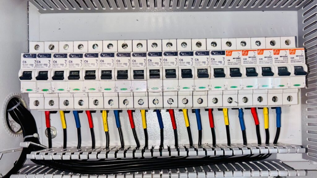
Featured visual: “Automated Factory Conveyor System in Operation” by Freek Wolsink, via Pexels, used under the Pexels licence. The photograph is a generic industrial automation image and does not depict a Titania installation or imply endorsement.