
When a remote I/O node answers Modbus requests, the integration is not necessarily commissioned. A register can change while the wrong field device is connected; an output indicator can illuminate while the load supply is absent. Titania remote I/O point-to-point commissioning should prove the entire signal chain before a machine is released to operations.
The Titania Modbus DI-8 DO-8 reference design provides eight digital inputs and eight high-side digital outputs with isolated RS-485 Modbus RTU communications. This procedure is a practical test method for that documented variant, not a substitute for the approved electrical drawings, risk assessment or firmware-matched register map.
1. Freeze the configuration and prepare a test boundary
Start with an approved I/O schedule listing terminal, cable core, field device, expected electrical state, Modbus item, PLC tag, HMI indication and response to loss of communications. Record hardware identity, firmware profile, slave address, serial framing and the applicable drawing and datasheet revisions. Check the physical DIP switch state against the documented operating mode.
Before touching an output, obtain the plant’s test authorisation and isolate or otherwise control any mechanism that could move, heat, pressurise or release energy. A PLC software inhibit alone is not an adequate substitute for the isolation procedure. Use approved test equipment and personnel.
2. Prove each digital input from field device to HMI
For DI1 through DI8, change one safe field condition at a time. The model documentation covers dry contacts and configurable PNP/NPN input arrangements: confirm the applicable common and polarity against the installed wiring diagram rather than assuming every input is active-high.
- Record the initial terminal condition and input status LED.
- Operate the identified sensor or contact through its safe test method.
- Check the module’s raw input state in the approved Modbus register or bit map.
- Confirm the PLC tag and HMI indication change in the intended direction.
- Return the device to normal and prove the return transition as well.
For a pulse or counter input, a static on/off check is insufficient. Verify edge polarity, input filtering and expected counting over a controlled test interval. Do not infer a reliable high-speed count solely from what a slowly scanned HMI displays.
3. Prove digital outputs without unintended actuation
The documented DO1–DO8 are 24 VDC high-side sourcing outputs. Under an authorised, isolated test arrangement, command one channel at a time and compare the requested state, module output indication and measured load-circuit voltage or approved test-load response. Then remove the command and prove the off state. Keep the output field supply, load return, protective devices and any separate actuator enable conditions in the test record.
Do not use an unprotected improvised load to demonstrate an output’s short-circuit or thermal limiting behaviour. A protected electronic output is not, by that fact alone, a safety-rated switching device. Any application involving emergency-stop or guard functions requires a separately engineered and validated safety architecture.
4. Test communications and stale-data handling
With field states stable, verify repeated reads over the actual PLC or IPC Modbus RTU master, not only a laptop test utility. Check device identity, the assigned slave address, data type and register-base convention. Where a displayed address uses a 3xxxx or 4xxxx prefix, confirm whether the PLC driver expects an offset or a human-readable reference; do not shift the register map by guesswork.
Temporarily remove the communications path only within an approved test window. Confirm that the supervisory system marks data as invalid or stale, raises the correct fault and follows the documented outputs-on-timeout behaviour. Restore the link and verify controlled recovery. A stale value that remains on the HMI as though it were fresh is a commissioning defect.
5. Account for local logic and restart behaviour
Titania has selectable local functional modes. A locally executed Boolean rule or sequencer may influence the output independently of a PLC command. The acceptance sheet should therefore identify which function owns each output during the test. Prove the approved start-up values and communication-loss values; power-cycle checks must be planned so they cannot energise a real actuator unexpectedly. Configuration changes should be read back and tested again after the prescribed save and restart procedure.
Point-to-point acceptance record
| Test item | Minimum evidence | Acceptance criterion |
|---|---|---|
| Input DI1–DI8 | Terminal, LED, Modbus state, PLC/HMI tag | Correct active and return transitions for every mapped channel |
| Output DO1–DO8 | Command, indicator, measured test-load response | Only intended output responds; off state is confirmed |
| Modbus identity | Unit ID, serial settings, revision-matched register map | Consistent readback through the production master |
| Link interruption | Timeout observation, stale-data alarm, recovery | Documented non-communications state occurs |
| Power restoration | Initial output state, logic mode, PLC reconciliation | Recorded behaviour matches the approved risk assessment |
Record pass/fail, measured observations, discrepancies, corrective actions, tester and witness. A screenshot of a green communications indicator is useful supporting evidence; it is not a substitute for the point-to-point record.
Handover means reproducible evidence
Release the system only when the revised I/O schedule, marked-up drawings, module identity, firmware/register-map reference, serial settings, output ownership, fault-state tests and outstanding punch-list are accounted for. Related technical guidance includes Titania device identity checks, output fault diagnostics and Modbus RTU commissioning.
For a model-specific channel schedule, approved register map or integration review, contact Tachyonic Intelligence’s engineering team.
Technical basis: Titania Modbus DI-8 DO-8 datasheet TTN-DS-2026-001 (controlled Rev 08, uploaded 22 July 2026) and the Modbus Serial Line Implementation Guide V1.02. Verify the controlled issue and firmware/register-map revision against the installed hardware before design freeze. No safety certification is implied.
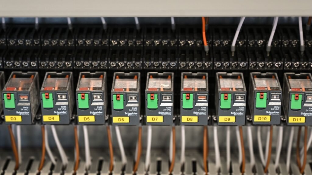
Image: Industrial control-panel photograph by ranjeet . via Pexels, used under the Pexels licence. Illustrative panel, not a photograph of a Titania installation.