
Titania Boolean logic commissioning should start with a truth table that an electrician, controls engineer and maintenance technician can all read. Titania provides local logic using an input mask, gate mode, input polarity and pattern-match behaviour mapped to output actions. Those functions can simplify a small, well-bounded control task, but only when the installed wiring and the configured logic have been tested together.
The objective is not to reproduce a PLC program inside remote I/O. It is to define one local decision clearly, prove every input combination that matters, and document how the output behaves during startup, communications loss and maintenance.
Titania Boolean logic commissioning begins with a truth table
Describe the required behaviour before writing a mask or selecting a gate mode. Give every physical input a machine name, state whether the field contact is open or closed in the normal condition, and define the output state expected for each relevant combination.
A useful table records:
- the Titania input channel and terminal reference;
- the field device, such as a pressure switch, auxiliary contact or position sensor;
- the electrically observed state for normal and active conditions;
- the logical state after polarity handling;
- whether the channel participates in the local decision;
- the expected output action;
- the PLC or SCADA indication that should agree with the local result.
Do not leave an untested combination simply because it is not expected in normal operation. Two field devices can disagree during wiring faults, maintenance or a slow mechanical transition. The truth table should state whether that combination produces an output, inhibits it or requires host-level handling.
Use the input mask to define the logic boundary
The input mask selects which channels participate in the local function. Confirm channel order against the released terminal drawing and the firmware-specific register map. A mask copied from another panel can be wrong even when the machines look identical, particularly after field wiring or firmware changes.
Commission the inputs as ordinary digital points before enabling local logic. Operate each field device separately, confirm its Titania channel indication and read the corresponding state over Modbus. Record any normally closed circuits, shared commons or interposing relays that affect the observed state.
When the physical mapping is proven, write the intended mask and read it back. Exercise both selected and unselected channels. An unselected input should remain visible to the host if the application reads it, but it must not change the local result.
Normalise active-high and active-low signals
Input polarity allows field signals with different electrical conventions to be interpreted consistently by the logic function. This is especially useful where one device closes on demand while another opens on fault or loss of power.
Polarity is not a substitute for correct wiring documentation. The commissioning record should show the raw electrical state and the logical state used by the local function. Without both, a later technician may “correct” an inversion that was deliberate.
Test polarity one input at a time. Hold the other participating inputs in a known condition, operate the selected field device, and confirm the resulting logical decision. Repeat after the approved save and restart procedure if the configuration is intended to persist.
Select the gate mode from the released register map
The controlled Titania datasheet confirms a configurable gate mode but does not define a universal enumeration for every firmware release. Use the register map that matches the installed hardware and firmware, and verify the selected mode by behaviour rather than relying only on a successful Modbus write.
Begin with test loads or an isolated output interface. Apply known input combinations from the truth table and record the output result. If a service tool displays a descriptive gate name, keep the underlying register value and the tool version in the commissioning record as well.
For a decision involving several inputs, check the order in which they change. A steady-state truth table does not describe the brief transition that occurs when one sensor changes before another. If that transition must be filtered, timed or latched, confirm the required behaviour is supported by the applicable function profile. Otherwise, keep the decision in the PLC where timing and state management can be reviewed explicitly.
Pattern matching needs exact state definitions
Pattern matching compares the participating inputs with a configured state pattern. It is suitable for recognising a defined combination, such as a machine-position state or a group of auxiliary contacts, provided every bit has a documented meaning.
Prove the expected pattern first, then test near matches by changing one input at a time. A good acceptance test confirms that the intended combination operates the output and that each single-bit deviation does not. Also test the all-off and all-on conditions, even when neither is expected during production.
A changing machine may pass briefly through the target pattern. If a momentary match could create an unwanted action, evaluate the input filters, scan behaviour and host-level sequencing required by the application. Do not assume a pulse will be ignored merely because it is short.
Assign one controller as the output owner
Direct Modbus output commands and local logic should not compete for the same channel without a documented priority model. Define whether the PLC enables the local function, monitors it, overrides it or remains completely outside the output path.
Maintenance mode needs the same clarity. A technician must be able to disable autonomous behaviour before forcing or testing an output. The procedure should prevent a local decision from re-energising a channel after the host or service tool has switched it off.
For cyclic output behaviour, use the separate Titania sequencer commissioning guide. For output electrical problems, follow the Titania output fault diagnostic procedure so a load fault is not misdiagnosed as a logic error.
Keep safety functions outside the local logic layer
Titania’s local logic and autonomous modes are control conveniences, not certified safety functions. Emergency stops, guards, burner-management trips and other safety-related interlocks require an independently designed and validated safety system.
A local logic function may support indication, permissive monitoring or a standard machine-control task when the risk assessment allows it. It must not be presented as the sole protective measure for a hazardous condition.
Test startup and communications-loss behaviour separately
Local logic does not remove the need to define power-up and communications-loss states. Titania provides programmable startup and safe values for its outputs, plus configurable watchdog supervision. Establish how those settings interact with the selected logic profile for the installed firmware.
Test at least four boundaries under controlled conditions:
- Cold power-up: observe the output before communications are established and before the host enables normal operation.
- Logic enable: confirm the output changes only when the documented input condition is present.
- Communications loss: interrupt the Modbus master and verify the configured watchdog and output policy.
- Recovery: restore communications and confirm whether the host, local logic or an operator action returns the output to service.
The Titania safe-state commissioning article covers the distinction between power-up and communications-loss behaviour in more detail.
A practical acceptance sequence
- Record the device code, hardware and firmware revision, serial number and register-map revision.
- Prove each input and output as conventional I/O before enabling local logic.
- Review the truth table with controls, electrical and maintenance personnel.
- Write and read back the input mask, polarity and firmware-defined gate or pattern settings.
- Test each participating input individually with the field load isolated or made safe.
- Run every relevant truth-table combination, including abnormal and near-match states.
- Test transition order, input filtering and any momentary pattern matches.
- Verify startup, watchdog, communications-loss and recovery behaviour.
- Repeat the readback after the approved persistent-save and restart procedure where applicable.
- Archive the final values, observed results and responsible output owner with the panel documentation.
Use local logic only where the decision remains understandable
A suitable local function is small enough to describe on one page, uses clearly identified signals and has predictable interruption behaviour. When the decision depends on several machines, recipe state, analogue conditions, long timing sequences or coordinated recovery, the PLC is usually the maintainable owner.
Review the Tachyonic product range, use the product selector, and keep the applicable files from the technical resources with the project release package.
Need a local-logic review before live commissioning? Send the Titania hardware and firmware revision, register-map revision, input/output schedule, truth table, field-device conventions and required failure behaviour for an engineering review.
Technical basis: Titania 8DI/8DO Industrial Super I/O datasheet TTN-DS-2026-001, Rev 08, issued 22 July 2026. The controlled source confirms input masks, gate mode, input polarity and pattern matching mapped to output actions. Exact enumerations, precedence, timing and persistence behaviour must follow the released firmware-specific register map.
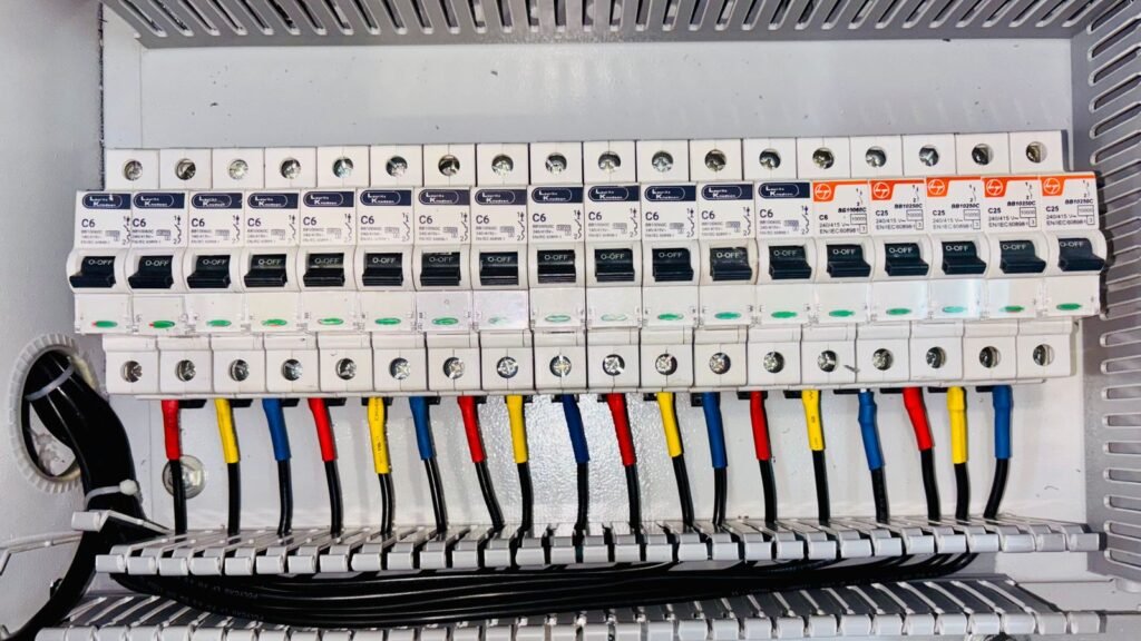
Featured visual: “Close up of Boxes with Wires” by Vladimir Srajber, via Pexels, used under the Pexels licence. The photograph shows generic industrial relays and does not depict Titania hardware or imply endorsement.