
Titania galvanic isolation separates the field-I/O, logic, RS-485 communications and power domains inside the remote-I/O architecture. That separation is useful in machines where sensor wiring, 24 VDC loads and a multi-drop serial network meet in the same cabinet, but it does not remove the need for a deliberate grounding, shielding and protection design.
The controlled Titania datasheet describes eight isolated digital inputs, eight protected high-side sourcing outputs and a transient-protected two-wire RS-485 interface. It does not publish an isolation-voltage rating in Rev 08. Panel designers should therefore use the released wiring information and final production declarations rather than substituting a value from an earlier draft or a component datasheet.
Titania galvanic isolation separates functional domains
The purpose of an isolation barrier is to limit unintended current paths between sections of a system. In Titania, the documented architecture separates field I/O, the internal logic core, RS-485 communications and power domains. This is more precise than saying that the module is simply “isolated”, because an engineer needs to know which circuits are separated before deciding where commons, shields and protective earth connections belong.
The architecture supports several different interfaces:
- eight digital inputs for dry contacts and wet-contact PNP or NPN devices;
- eight high-side sourcing outputs for suitable 24 VDC loads;
- a two-wire half-duplex RS-485 Modbus RTU port; and
- a nominal 24 VDC supply with a documented 19.2 to 28.8 VDC operating range.
Those interfaces can be exposed to different noise sources. Sensor cables may run beside motors, the output wiring may switch inductive loads, and the RS-485 trunk may extend beyond the local enclosure. Separation inside the module helps control how disturbances propagate, but cable routing and panel bonding still determine what reaches each terminal.
Isolation does not replace a wiring strategy
A common commissioning error is to treat every terminal marked COM, 0 V or shield as interchangeable. That can bridge an intended isolation boundary or create a parallel return path through cable screens, mounting hardware or another device.
Start with the released terminal and wiring drawing for the ordered hardware revision. Identify the reference used by the digital inputs, the return path for output loads, the module supply reference, the RS-485 pair and any communications common or shield connection provided by the installation design. Do not add links between these points simply because continuity appears convenient during bench testing.
Digital inputs
For dry contacts, PNP sensors and NPN sensors, wire the field device according to the selected input configuration. The controlled datasheet specifies the supported input types and their logic levels, but the final terminal assignment belongs to the released drawing. A PNP sensor requires the corresponding sinking-input arrangement; an NPN sensor requires the sourcing-input arrangement.
High-side outputs
Titania’s outputs source field power to the load. Keep the load-current path out of communications wiring and low-level input bundles. Inductive loads, inrush current, switching frequency, simultaneous channel loading and enclosure temperature must be reviewed together. Internal output protection does not replace external branch protection or a verified load design.
RS-485 trunk
Use a daisy-chain trunk with short stubs, termination at the two physical ends and one documented bias arrangement where required. Maintain A/B polarity and define the shield and common strategy for the whole network. Star wiring, multiple undocumented bias networks and shields grounded at arbitrary points make an isolation problem difficult to distinguish from a signalling problem.
Grounding and shielding belong to the complete machine
The correct shield connection depends on the plant grounding system, cable construction, equipment layout and applicable electrical rules. The module cannot make that decision in isolation from the rest of the machine.
Document where the cable shield terminates, whether it is bonded at one or more locations under the approved EMC design, and how the functional 0 V system relates to protective earth. Keep high-current switching conductors and motor/VFD cables away from the RS-485 pair and sensor wiring where practical. If cables cross, a short right-angle crossing is preferable to a long parallel route.
For a remote pump skid, for example, a local 24 VDC supply may power Titania and its field devices while RS-485 returns to a supervisory cabinet. The engineering record should show the local reference, shield termination, surge-protection arrangement, cable route and any intentional bond. Without that record, a later maintenance link can quietly create a new current path.
EMC design levels and isolation ratings are different claims
Rev 08 states source-design levels for electrostatic discharge, electrical fast transients and surge: ESD ±15 kV air and ±8 kV contact; EFT ±2 kV on power and ±1 kV on signal; surge ±1 kV differential and ±2 kV common mode. These values describe disturbance design levels stated in the controlled source. They are not an isolation-voltage specification and should not be presented as one.
Likewise, galvanic isolation does not automatically make an installation a safety circuit, an intrinsically safe circuit or a substitute for protective separation required by another standard. Safety-related interlocks and hazardous-area interfaces require a separately designed and validated solution.
Before design freeze, confirm the production isolation declaration, terminal drawing, applicable EMC declaration, creepage/clearance requirements and external protection for the ordered variant. If the project specification requires a particular working voltage, test voltage or certification, obtain that value from the controlled production documentation.
Commission each boundary deliberately
A useful acceptance test separates wiring faults from network and application faults:
- With power removed, compare every terminal and field reference against the released drawing.
- Check for unintended continuity between isolated references before connecting external cables.
- Energise the module from a protected supply and verify voltage at the terminals under expected load.
- Test each input type using its actual field-device wiring, not a temporary link that bypasses the intended reference.
- Operate one output load at a time, then the expected simultaneous combination, while observing current and enclosure conditions.
- Commission RS-485 at conservative timing and confirm termination, bias, shield and common arrangements.
- Record the final wiring, hardware revision, firmware revision and any intentional earth or common bonds.
If communication becomes unstable only when an output switches, investigate the physical installation before changing protocol settings repeatedly. Look at load suppression, supply impedance, cable routing, shield current and reference connections. The COM indicator and Modbus diagnostics can help locate the symptom, but they cannot correct an unintended current path.
Use isolation as part of the panel design
Titania’s separated domains are most useful when the surrounding installation preserves their intent. Treat isolation, EMC protection, wiring references, cable routing and external protection as one design problem. That produces a panel which is easier to commission and easier to diagnose when a field cable or load behaves unexpectedly.
Review Titania within the Tachyonic product range, compare the application with the product selector, and read the related guidance on Titania Modbus RTU commissioning and distributed I/O cabinet design. Broader deployment guidance is available in industrial automation solutions and technical resources.
Reviewing a noisy or distributed I/O panel? Send the field-device types, load schedule, supply arrangement, cable lengths, RS-485 topology and grounding constraints for an engineering review.
Technical basis: Titania 8DI/8DO Industrial Super I/O datasheet TTN-DS-2026-001, Rev 08, issued 22 July 2026. Confirm the released terminal drawing, production declarations and firmware/register-map revision for the installed hardware.
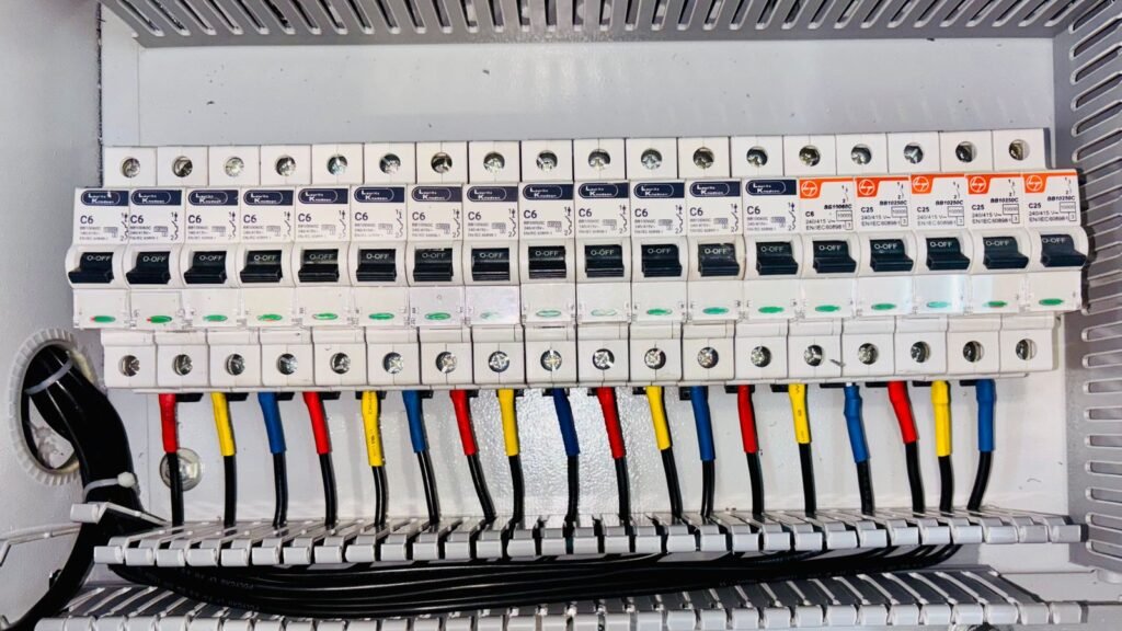
Featured image: electrical-panel wiring by Pixabay via Pexels, used under the Pexels licence. The photograph illustrates cabinet wiring practice and does not depict Titania hardware.