
After a motor bearing change, coupling adjustment or other rotating-equipment repair, a machine that runs quietly is not necessarily ready for handover. Its vibration pattern may have changed for entirely legitimate reasons: new bearing clearances, altered alignment, mounting work or a different running condition. Post-repair vibration verification with PyXis should establish what changed, whether the measurements can be trusted and which baseline may govern future alarms.
Use the following process as a commissioning and maintenance procedure, not as a claim that any single vibration reading certifies the repair. Electrical, mechanical and machine-safety checks remain separate acceptance requirements.
Keep the old history, but do not confuse it with the new reference
Preserve the last valid pre-maintenance trend, along with the defect report and repair work order. Those readings explain why intervention was undertaken; they are not automatically appropriate alarm thresholds for the repaired assembly. Mark the maintenance event on the historian and record the time at which the machine returned to service. This protects long-term trending from unexplained step changes.
Where the repair also alters motor speed, gear ratio, pulley arrangement or bearings, confirm the machine profile and associated configuration before interpreting any comparison. Our PyXis machine-profile configuration guide explains the data that should be checked.
1. Re-establish the measurement chain
Record the exact sensor location, measurement axis, mount type, cable route, machine tag and sensor/device identity. If the sensor was disturbed during maintenance, do not assume that the new measurement point is equivalent to the old one. Even a small change in mounting rigidity or orientation can affect the measured vibration. Inspect the surface, mounting security, cable strain relief and protection from accidental damage.
The controlled PyXis 222x Series datasheet identifies M5 stud and high-force magnetic mounting options, subject to the ordered variant and approved installation instructions. It does not provide a universal tightening torque. Refer to the released drawing and mounting selection guidance rather than inventing one on site.
2. Compare like operating conditions
Collect the new reference with the machine safely running in a defined state. Log speed, process load, operating temperature, duty cycle, valve or damper position where relevant, and any neighbouring machinery likely to influence the measurement. A fixed-speed pump running near its normal duty point is a better comparison with its previous equivalent state than with a low-load startup trace.
For variable-speed equipment, identify a small number of repeatable speed/load bands. Do not average disparate operating conditions into one reassuring number. Allow an appropriate stabilisation period defined by the equipment and maintenance procedure; do not treat a transient during run-up as the steady-state baseline.
3. Validate the data before drawing conclusions
At each agreed operating state, capture the available vibration indicators and temperature, the observation period, and a note of any audible noise, leakage or abnormal heating. Where reliable rotational data are available, record them alongside the trend. Confirm sensor communications, timestamps, expected update behaviour, units and any invalid or stale values before accepting the capture.
If PyXis data are collected over Modbus RTU, check the actual device identity, installed firmware, configuration and its matching register map. A register address, scaling factor, diagnostic index or refresh interval should never be carried over from another revision merely because a dashboard displays a number. Record the PLC/SCADA tag mapping and identify communications faults distinctly from healthy readings.
4. Decide whether the post-repair condition is acceptable
Review the pattern across available axes, operating states and multiple repeatable observations rather than relying on a single peak. A lower vibration value after repair may be encouraging, but it is not proof of correct lubrication, alignment, bearing fit or electrical integrity. Conversely, an increase needs investigation before it becomes the new normal. Evaluate the relevant machine manufacturer’s acceptance criteria and any applicable, correctly scoped vibration standard using the approved site procedure.
Document deviations as a punch-list: suspected mechanical cause, required inspection, responsible engineer and retest condition. If baseline quality is uncertain, leave it explicitly provisional. Do not silently widen the alarm limits just to clear an alarm after maintenance.
5. Release the baseline under change control
Once the equipment and data have passed review, retain both the former historical reference and the approved post-repair baseline with a unique revision, effective date, operating envelope and approver. Test the PLC/SCADA handling of warning, invalid-data and communications-loss states. Any safety trip or machine-protection function requires its own risk assessment and validated control architecture; condition-monitoring indications should not be presented as a safety-rated protective system.
A practical handover pack contains the work-order reference, before/after measurement plots, machine operating state, sensor location photograph, device/firmware and register-map identification, revised alarm settings, open deviations and maintenance sign-off. This creates an auditable reason for subsequent trend changes instead of forcing the next shift to reconstruct what happened.
For assistance specifying a post-maintenance verification procedure or integrating PyXis readings into an industrial PLC or historian, contact Tachyonic Intelligence’s engineering team with the machine type, maintenance scope, sensor arrangement and controller platform.
Technical basis: PyXis 222x Series Datasheet TTN-DS-2026-002, controlled Rev 08. Confirm the released variant-specific installation documentation and firmware-matched Modbus register map before commissioning. This article is engineering guidance, not a machine-specific acceptance certificate.
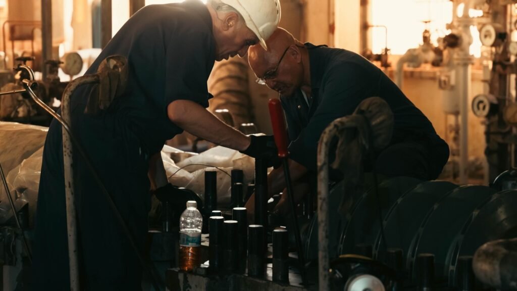
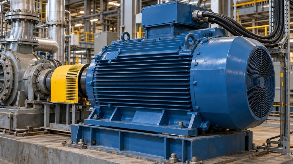
Image credit: Industrial-plant engineering photograph by abdo alshreef via Pexels, used under the Pexels licence. Illustrative industrial machinery; not a documented PyXis installation or an actual post-repair test.