
PyXis persistent configuration deserves the same change control as a PLC program. A commissioning engineer may set the Modbus address, serial format, machine profile, analysis filters and alarm thresholds correctly, then discover after a restart that the running values and the retained values were not treated as the same thing.
The PyXis register model includes common holding registers for communication settings and lifecycle commands, including persistent save, reboot and factory reset. Those controls are useful during commissioning and service, but they should never be issued casually from a normal SCADA screen. The released Modbus register map and firmware release note define the command values, availability and response sequence for the installed unit.
PyXis persistent configuration is a controlled commissioning step
Configuration work normally begins with writable settings such as slave ID, baud selection, parity and stop-bit format, response delay, machine profile, motor frequency, gear and bearing data, analysis filters and warning or alarm thresholds. Some projects expose only a subset of these items to the PLC; others use an engineering tool or gateway during setup.
Whatever the host platform, separate three states in the commissioning record:
- planned values approved for the asset;
- values currently read back from PyXis; and
- values verified after a controlled restart.
A successful Modbus write proves that a request was accepted at that moment. It does not, by itself, prove that every related value has been validated, saved to non-volatile storage or restored after power cycling. Persistence should therefore be an explicit test, not an assumption.
Keep save, reboot and factory reset outside normal control logic
The controlled datasheet identifies persistent save, reboot and factory reset as lifecycle commands in the common management area. These are maintenance actions, not ordinary process commands.
Persistent save
Use the command sequence defined by the firmware-matched register map only after the complete configuration has been written and read back. Record the approved values before the save request, then verify them again after the device has completed the documented apply or restart sequence.
Reboot
A reboot interrupts normal data availability. The PLC or gateway should mark vibration, temperature and condition values as unavailable or stale until communication has recovered and the device identity and configuration checks have passed. Do not hold the last received condition value on screen without a separate quality indication.
Factory reset
A factory reset can invalidate the commissioned address, serial settings, machine context, filters and thresholds. Restrict it to authorised maintenance, capture the as-found configuration first, and have a documented recovery route. The recovery plan must use the command definitions and defaults stated for the installed firmware rather than values copied from another unit or an older workbook.
A verification sequence for commissioning
A practical workflow keeps the network recoverable while proving that the intended settings survive:
- Identify the unit. Read and record the device code, hardware revision, firmware revision, manufacturing date and serial number.
- Match the documentation. Confirm that the Modbus register-map revision applies to that firmware. Do not infer units, scaling, signedness or enumerations from register names.
- Export the as-found state. Capture communication settings, machine profile, analysis filters and thresholds before making changes.
- Write one controlled set. Apply the approved values using the access functions specified by the released map, then read every value back.
- Save through the documented lifecycle control. Observe the stated response and settling requirements for that firmware.
- Restart under supervision. Expect a temporary loss of Modbus data and suppress nuisance alarms without suppressing the communication-quality indication.
- Read back after recovery. Confirm identity, communications, machine context, filters and thresholds against the approved record.
- Release the point to service. Update the asset history with the date, engineer, firmware, register-map revision and final settings.
When a communication-setting change could make the current master lose contact, plan the new address and serial format before issuing the save or restart command. Keep a direct local recovery method available and change one network node at a time. On a multi-drop RS-485 trunk, duplicate addresses or undocumented baud changes can affect more than the sensor being commissioned.
Design the PLC interface around configuration authority
Most operating HMIs do not need unrestricted access to lifecycle commands. A safer interface separates monitoring from engineering access:
- normal users read condition, identity and configuration state;
- authorised engineers may edit an approved set of parameters;
- save, reboot and reset require a distinct maintenance mode and deliberate confirmation;
- the host logs the user, time, old value, new value and verification result; and
- the PLC treats post-command data as invalid until communication and identity checks succeed.
For a remote pump station or an unattended fan, this discipline is particularly important. A poorly controlled restart can remove condition visibility until somebody visits the site. A controlled sequence leaves the last known value in the historian for traceability while clearly marking the live point as stale until PyXis returns.
Firmware and register-map limits must remain visible
PyXis supports a broad register-backed data model, including condition metrics, harmonics, rotational context and firmware-dependent diagnostic or prognostic extensions. That does not make every register universal across all releases.
Before design freeze or a service change, confirm the installed firmware, the matching register map, command access, data scaling and the availability of the required functions. Do not build a generic reset routine around an assumed register address or command code. If a project needs centrally managed configuration across many sensors, define version control, access rights and rollback records as part of the integration scope.
Review the PyXis product within the Tachyonic sensor range, compare the application with the product selector, and see the related guidance on PyXis identity registers and Modbus condition-monitoring integration. Broader deployment guidance is available in industrial monitoring solutions and technical resources.
Planning a controlled PyXis configuration workflow? Send the sensor count, controller platform, firmware and register-map revision, intended configuration ownership and recovery requirements for an engineering review.
Technical basis: PyXis 222x Series datasheet TTN-DS-2026-002, Rev 08, issued 22 July 2026. Confirm the installed hardware, firmware and matching Modbus register map before commissioning or issuing lifecycle commands.
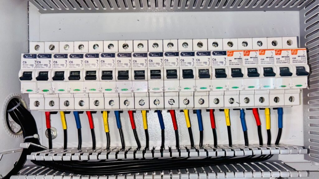
Featured image: industrial control-panel commissioning by Visen Group via Pexels, used under the Pexels licence. The photograph illustrates controlled configuration work and does not depict PyXis hardware.