
PyXis diagnostic index commissioning is the step that turns advanced vibration indicators into dependable PLC, SCADA and historian data. PyXis can expose firmware-dependent values such as envelope kurtosis, sideband density, harmonic consistency, a cepstrum gear index, spectral kurtosis and a cyclostationary index. Each condenses a particular pattern in the measured vibration, but none should be treated as a universal fault code.
The integration needs more than a register address. The host must retain the firmware and register-map revision, decode each value with the released data type and scale, confirm when it updates, and establish how it behaves under representative machine speed and load. Without that discipline, a plausible number can still be the wrong number.
PyXis diagnostic index commissioning begins with release control
The controlled PyXis datasheet describes the diagnostic indices as firmware-profile-dependent capabilities. Detailed implementation therefore starts with the delivered device, not with a generic register list. Read and record the device code, hardware revision, firmware revision, manufacturing date and serial number before mapping any advanced value.
Use the register map and firmware release note that match that identity. They define the applicable addresses, data types, word order, scaling, signedness, units or dimensionless representation, enumerations and supported update behaviour. If any of those details are absent, leave the item uncommissioned rather than filling the gap by assumption.
The PyXis device identity register guide provides a practical structure for keeping this version information with the asset record.
Assign a specific engineering role to each index
Advanced indicators are most useful when the project defines what evidence each one contributes. Their names describe signal-processing approaches, not guaranteed diagnoses:
- Envelope kurtosis can help screen for impulsive behaviour after the signal has been conditioned around a selected band.
- Sideband density can indicate how modulation components are distributed around dominant spectral features.
- Harmonic consistency can show whether expected harmonic relationships remain stable.
- Cepstrum gear index can emphasise repeating spectral spacing associated with geared-machine behaviour.
- Spectral kurtosis can help identify frequency regions containing non-stationary impulsive energy.
- Cyclostationary index can highlight statistical behaviour that repeats with the machine cycle.
These are screening and trending tools. Process impacts, load changes, looseness, mounting stiffness, speed variation and unrelated mechanical events can influence them. A rising value should open an investigation with supporting measurements; it should not automatically label a bearing, gear or alignment fault.
For additional signal-processing context, see Advanced Vibration Condition Indicators Explained. The commissioning task covered here is narrower: proving that the correct PyXis value reaches the supervisory system with sufficient quality and operating context.
Build the PLC or gateway tag around data quality
A single floating-point tag is not enough for a maintainable integration. For every enabled index, retain a small record containing:
- raw register words and decoded value;
- device serial number and firmware revision;
- register-map revision used by the decoder;
- host timestamp and communication quality;
- update or freshness state defined for the installed firmware profile;
- axis or analysis context where the released map assigns one;
- machine speed, load or operating state available at acquisition;
- baseline state and relevant filter or machine-profile revision.
Keeping the raw words alongside the decoded value makes commissioning and later regression tests much easier. If a firmware update changes a data definition, the stored record can reveal whether the change came from the machine or from the decoder.
Do not reuse a stale diagnostic value
Communication health must be evaluated before machine condition. A Modbus timeout, partial read or retained PLC memory can leave the last good value visible after new data has stopped arriving. The supervisory layer should distinguish a current value, a stale retained value, an unsupported item and a decoding error. None of those failure states should be presented as “normal”.
PyXis uses a two-wire half-duplex RS-485 Modbus RTU interface. Poll intervals and stale-data limits must be chosen around the actual update behaviour of the installed firmware profile and enabled analysis functions. The controlled datasheet does not justify a universal refresh time.
Baseline the indicators under comparable operation
A diagnostic index becomes useful when its normal variation is understood. Capture representative healthy operation across the machine’s normal speed and load range, then retain those operating labels with the trend. One baseline collected at idle is a poor reference for a machine that normally runs under changing production load.
Before collecting the baseline, stabilise the physical installation and configuration:
- confirm sensor mounting and axis orientation;
- record motor frequency, gear ratio, tooth counts and bearing geometry where used;
- verify high-pass and low-pass filter settings;
- check RPM, tachometer quality and speed state where available;
- record maintenance condition and recent mechanical changes.
The PyXis machine profile configuration guide covers the machine-reference data, while the PyXis vibration filter guide explains how filter choices affect the evidence reaching the analysis layer.
Trend the index before assigning an alarm
An index may be dimensionless or use a firmware-specific representation. That alone does not provide a defensible warning threshold. Start by observing repeatability at stable operating points and the spread across normal operation. Compare any change with X, Y and Z acceleration, velocity, displacement, crest factor, harmonic data, temperature and rotational context.
A useful maintenance rule can require both persistence and corroboration. For example, an index change may generate a review request only when it remains outside its commissioned baseline band and a related vibration or spectral measure also changes under comparable speed and load. The exact logic belongs to the plant’s validated maintenance procedure; it is not a universal PyXis setting.
Keep condition-state alarming separate from data-quality alarming. The PyXis fault-state integration guide shows how severity, supporting evidence and stale-data handling can be presented together.
Acceptance testing from sensor to historian
- Confirm identity. Read the device and firmware information and match it to the controlled register map.
- Prove the decoder. Check data type, word order, scaling and supported range against released test data or an approved engineering reference.
- Check availability. Verify which indices the installed firmware profile actually exposes.
- Observe stable operation. Acquire repeated values at a steady, documented speed and load and confirm plausible repeatability.
- Change operating context safely. Where normal production permits, compare another documented speed or load without simulating a mechanical defect.
- Interrupt communications. Confirm that the PLC, SCADA and historian mark the value stale or unavailable instead of retaining it as current.
- Restart under control. Verify the expected post-reboot availability and freshness behaviour without inventing a fixed warm-up time.
- Check the complete record. Confirm that the historian receives the value, timestamp, quality, operating context and revision information together.
- Freeze the release. Retain the firmware, register map, tag database, baseline conditions and acceptance results under change control.
Defined limits for advanced indicators
PyXis diagnostic indices provide compact condition evidence over Modbus. They do not replace raw-waveform acquisition, a full high-resolution spectrum or specialist vibration analysis where those are required. Availability and behaviour depend on the installed firmware profile, and the controlled datasheet does not define universal alarm thresholds for these indices.
Mounting, speed, load, machine geometry, filtering and baseline quality remain part of the interpretation. PyXis is also a condition-monitoring device, not a certified safety function. Any protective trip or safety-related interlock requires a separately designed and validated safety system.
Projects that benefit from this integration
This approach suits machine builders, system integrators and maintenance teams that want advanced condition evidence in a PLC, SCADA, historian or CMMS workflow without continuously transporting raw vibration waveforms. It is especially relevant where firmware changes, fleet-wide tag standards or multiple operating states make traceability important.
Review the Tachyonic product range, compare options with the product selector, and retain the matching files from the technical resources before design freeze.
Preparing a PyXis diagnostic-data integration? Send the firmware and register-map revision, controller or gateway, required indices, machine operating states, polling interval and historian structure for an engineering review.
Technical basis: PyXis 222x Series datasheet TTN-DS-2026-002, Rev 08, issued 22 July 2026. Verified capabilities include firmware-dependent envelope kurtosis, sideband density, harmonic consistency, cepstrum gear index, spectral kurtosis and cyclostationary index. Exact addresses, data types, scaling, availability and update behaviour require the matching register map and firmware release note.
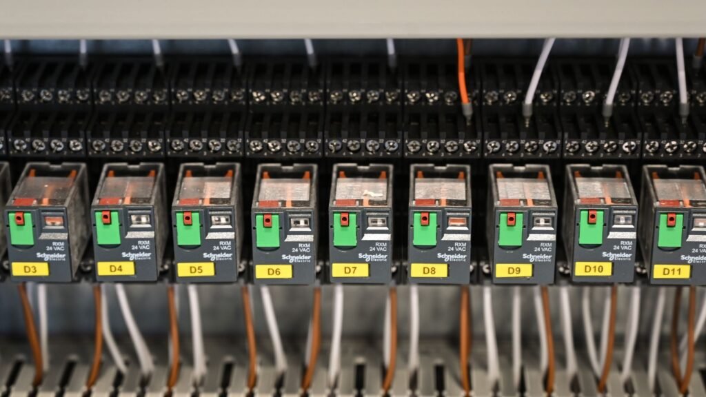
Featured visual: “Engineer at Control Room Monitoring Screens” by Sergey Sergeev, via Pexels, used under the Pexels licence. The photograph illustrates supervisory data review and does not depict PyXis hardware or a Tachyonic deployment.