
An alarm that turns on and off repeatedly is not necessarily evidence that a motor has suffered repeated faults. A vibration value hovering near a threshold can produce a stream of apparent incidents even while the mechanical condition remains essentially unchanged. At the other extreme, excessive filtering may hide a real deterioration. For engineers integrating PyXis motor monitoring into a PLC, SCADA or maintenance system, the right task is to separate the measurement from the alarm decision.
Why alarms chatter at a threshold
Consider a vibration measurement alternating between slightly below and slightly above a selected review threshold. Variation may come from load changes, speed, sensor mounting, genuine periodic machine motion, electrical interference or measurement uncertainty. A threshold with no state memory treats every crossing as a new alarm condition. The operator may see dozens of alarms where only one near-threshold episode exists. The fact that a trend appears smooth on the HMI does not prove that the underlying samples are steady: graph aggregation and screen refresh can conceal short fluctuations.
Before changing any alarm setting, record the measurement quantity and units, sensor location and axis, sampling/aggregation period, machine speed and operating regime. A velocity-RMS reading, acceleration peak and frequency-domain indicator are different measurements; their numeric thresholds are not interchangeable. Do not borrow another motor’s limits simply because both machines use a vibration sensor.
Hysteresis and persistence solve different problems
Hysteresis gives an alarm separate entry and exit thresholds. In a hypothetical logic example, a warning might enter when a measurement rises above 4 units and remain active until it falls below 3.5 units. The values are illustrative logic numbers only, not PyXis settings, an ISO alarm recommendation or a safe limit for any machine. Hysteresis prevents rapid state changes around a single cut-off.
Persistence time means a condition must remain true for a configured interval before raising or clearing an alarm. It addresses brief transients. But delays have consequences: a genuine quickly developing problem can be detected later, and slow SCADA polling may miss an event altogether. An alarm-on delay should therefore be justified against the required reaction time, while a separate event-history path may retain the raw threshold crossing for diagnostics.
Filtering changes the observed signal; hysteresis and delays change the decision. Do not substitute a long moving average for a missing alarm-state design. When the machine accelerates or changes production load, a valid state-based inhibit or distinct operating baseline may be more defensible than ever-growing delay values.
A commissioning test that produces evidence
- Record the baseline: capture vibration trend alongside speed, load or process state and the sensor mounting position. Check that the signal is not stale.
- Prove the raw value: compare the device-side indicated quantity, exported interface value and SCADA engineering unit. Confirm any scaling and timestamps.
- Simulate crossings: in an authorised test or software simulation, move the input just above and below the configured entry threshold. Verify alarm activation and whether repeated crossings create a single episode or many.
- Prove recovery: test the separate clear threshold, acknowledge state and the difference between an active fault, a latched event and an operator acknowledgement.
- Test operating modes: compare start-up, coast-down, normal steady running and planned load changes. Apply mode-specific logic only when a documented machine condition justifies it.
- Test communications faults: disconnect or simulate loss of the data source. An invalid or stale sample must not silently appear as a healthy zero vibration.
Where PyXis and the supervisory system fit
PyXis is a motor-condition-monitoring product family; confirm the installed product and controlled datasheet, firmware revision, documented output quantities and communication interface before configuring any project-specific thresholds. This article describes a general supervisory alarm-design method, not a claim that every PyXis hardware or firmware revision implements device-side hysteresis, delays or particular programmable alarm registers. Where the device does not provide a required function, the designated PLC or SCADA can implement authorised supervisory logic subject to a reviewed alarm philosophy.
For a robust maintenance workflow, preserve unmodified sampled data and an independently timestamped alarm history so technicians can examine why the warning occurred. A repeated warning is an invitation to investigate real machine conditions, sensor attachment, cable integrity and the logic itself; it is not proof of a bearing defect or a reason to defeat independent equipment protection.
Further reading: Motor start-up vibration and transient interpretation; motor soft foot and trustworthy baselines; event timestamp integrity across PLC and SCADA. These are practical engineering guides, not substitutes for the equipment maker’s limits or a machine-specific risk assessment.
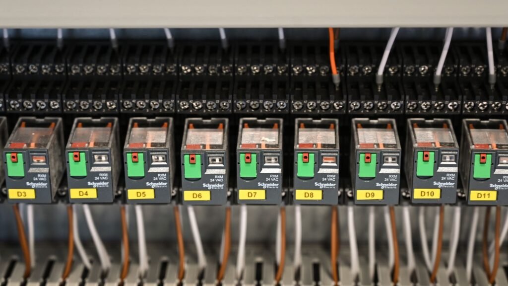
Photograph: illustrative engineering inspection scene, site-hosted Pexels image #37668543. Photographer and usage rights must be verified against the original Pexels listing before reuse beyond the existing authorised site asset; the photograph does not depict a tested PyXis installation. For product-specific wiring, firmware and alarm-engineering assistance, contact Tachyonic Intelligence.