
A motor overload relay may have an auxiliary contact for indication, but that contact must not be confused with the device that actually interrupts a hazardous or damaging condition. Connecting the indication to a remote-I/O module improves diagnostics only when the original protective circuit remains independent. For a Titania 8DI/8DO installation, the design question is how to bring a motor starter’s status into PLC and SCADA records without making network availability part of the protection function.
Distinguish trip action from trip indication
On a conventional starter, a properly selected and configured protection device acts through its approved control circuit. A separate auxiliary contact can indicate that the overload relay has operated. Whether a particular contact is normally open, normally closed or mechanically linked to a specific fault condition depends on the actual starter and relay model; check its schematic and manufacturer’s instructions before specifying a digital input.
The Titania module should observe that indication as standard monitoring I/O. It must not be used as a substitute for required motor overload protection, emergency stop or a separately validated functional-safety system. A working PLC screen cannot prove that the independent trip circuit is healthy.
Prepare an unambiguous point schedule
Record the source terminal references, contact function, normal state, expected tripped state, field voltage, input reference and cable destination. Give the point a functional tag such as MTR-101 overload operated rather than an ambiguous label such as motor fault. Distinguish overload operation from loss of a signal wire, controller power loss and an actual running-state indication.
Use the issued Titania 8DI/8DO controlled datasheet, TTN-DS-2026-001 Rev 08, together with the installed terminal drawing, to check the input interface before wiring. Do not assume a dry contact can be connected in any polarity, or that all similarly labelled terminals share the same common. Confirm the installed hardware and firmware revision against its released register map before commissioning PLC addressing, polarity or any software filtering.
Design the alarm for useful diagnosis
At the PLC, convert the validated electrical input state into an explicit alarm meaning. Retain at least the source-point quality, observed state, event timestamp, acknowledgement status and communications health. If a valid Modbus RTU response is absent, report data unavailable rather than treating the last sampled overload contact as a fresh, healthy indication.
Alarm latching and reset must follow the motor starter’s approved control philosophy. Clearing a SCADA acknowledgement must never remotely defeat the physical overload mechanism or permit an unintended restart. For applications that require an operator reset after a trip, confirm the behaviour with the equipment’s responsible engineer rather than relying on a display-level setting.
Where mechanical contacts bounce or exhibit short transitions, record the actual signal behaviour and determine any debounce or alarm persistence at the correct control-system layer. Do not assume a specific Titania firmware filter feature or time base without the controlled register map. Excessive filtering can hide a short but important event.
Acceptance tests that distinguish the failure modes
- Verify the as-built circuit. Compare the overload relay’s approved diagram, auxiliary-contact designation, field supply, Titania terminal and PLC tag. Confirm protection is wired independently.
- Prove the normal indication. With the machine in a permitted state, observe the physical contact and matching input status. Record the expected healthy alarm state.
- Simulate or test a trip safely. Use only the protection manufacturer’s approved test procedure and site authorisation. Observe protective action, local indication, PLC alarm and operator acknowledgement. Never create an actual overload simply to prove telemetry.
- Test a communication interruption. Under controlled conditions, make the master lose valid status data. Confirm the HMI marks the input stale and does not silently display a healthy motor condition.
- Verify reset and recovery. Restore communication and reset the protective device only through its approved procedure. Confirm no unplanned automatic motor restart occurs.
- Retain the evidence. Save terminal references, relay model, firmware identity, register-map revision, witnessed transitions, timestamps and corrective actions in the handover record.
Our Titania communications-loss and safe-state guide provides context for distinguishing remote-control behaviour from independent protection. For broader proof of real equipment response, consult the actuator-feedback commissioning guide.
Handover what the operator can trust
A reliable overload alarm is a documented chain from a defined physical contact through a correctly configured input, a valid network sample and an explicitly qualified HMI indication. It is not a claim that the remote-I/O device itself provides motor protection. For help reviewing starter signals and remote-I/O integration, contact Tachyonic Intelligence with the motor-starter schematic and I/O schedule.
Technical references and limitations: Titania 8DI/8DO Datasheet, TTN-DS-2026-001 Rev 08; MODBUS over Serial Line Specification and Implementation Guide V1.02. Electrical input conditions, connector assignments, register interpretation, filtering and supported functionality must be checked against the installed hardware, firmware and issued documentation. No safety certification, register value or protective trip performance is asserted for Titania.
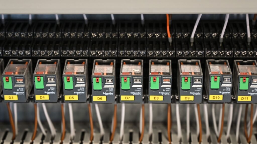
Image credit and disclaimer: “Close up of Boxes with Wires” by Vladimir Srajber / Pexels, reused from TISB’s existing site-hosted media under the Pexels licence. Illustrative industrial relay-panel photograph only; it does not show a verified Titania installation, a motor-overload test or an endorsement.