
A Modbus response can be perfectly valid and still contain the wrong measurement. The PLC receives a clean reply, the SCADA tag shows a number, and nobody notices that the master is reading the register next door. One of the oldest causes is a deceptively simple numbering convention: holding register 40001 is not normally sent as address 40001 on the wire.
This is not a new Modbus vulnerability or a defect in any particular I/O module. It is a documentation and configuration trap that still matters when technicians commission an industrial controller, remote I/O or vibration-monitoring device from a register table.
Why 40001 becomes zero
In the traditional five-digit Modicon reference notation, the leading 4 identifies the holding-register class. It is not part of the 16-bit starting address carried inside a function-code-03 Modbus request. The first holding register is reference 40001; its zero-based protocol data unit (PDU) address is 0. The hundredth holding register, reference 40100, has PDU address 99.
| Conventional reference | Function code | Zero-based PDU offset |
|---|---|---|
| 40001 | 03 — read holding registers | 0 (0x0000) |
| 40002 | 03 | 1 (0x0001) |
| 40100 | 03 | 99 (0x0063) |
| 30001 | 04 — read input registers | 0 (0x0000) |
These examples assume conventional one-based reference numbers. Some manufacturers document raw offsets directly; some software fields ask for a one-based register index; others accept the whole 40001 reference and convert internally. Six-digit notation such as 400001 makes the register class clearer for larger maps but does not by itself tell you whether the driver’s entry field wants 400001, 1 or 0. Check the application’s actual address syntax before interpreting any number.
What the device actually sees
A function-code-03 read request contains the device address (for RTU), function code, starting address and quantity. For the first holding register, the start-address bytes are 00 00, not the decimal number 40001. A request for the hundredth conventional holding register starts at 00 63 hex. A normal Modbus reply does not prove that the engineer selected the intended variable; it only proves that the device answered the requested location.
The same principle applies to input registers, but those are read using function code 04. Coils and discrete inputs have their own data classes and function codes. The legacy 3xxxx and 4xxxx prefixes are reference notation, not substitutes for confirming the supported function code and register map.
Why an off-by-one error can survive factory acceptance
Consider a documented motor-temperature value spanning two consecutive 16-bit registers. If the master begins one word late, it may combine half that value with half the next parameter and produce a plausible-looking floating-point number. Even correctly configured word order cannot repair a shifted register start. A digital fault bit can be equally misleading if a nearby holding-register value happens to remain constant during the test.
A technician should compare the expected physical variable, its register class, absolute or relative index, word count, signedness, scaling and byte/word order. Communication quality and measurement validity are separate acceptance criteria.
A safe five-point commissioning proof
- Freeze the register-map revision. Record the exact hardware and firmware revisions, manufacturer document revision, slave ID, serial settings and the PLC driver’s addressing convention.
- Pick a known read-only point. Use an identified status or measured value with a legitimate independent reference. Do not experiment with writable setpoints, output coils or control registers on running equipment.
- Capture a request and response. Record the function code and the transmitted two-byte start address. A HMI entry of 40001 is not enough evidence; inspect what the driver actually transmits.
- Prove a controlled change. Under an approved test procedure, compare a known change in the physical input or status to the intended PLC tag. Check adjacent registers for shifted mappings and validate 32-bit decoding separately.
- Record the as-tested mapping. Preserve the function code, zero-based PDU offset, driver input syntax, data type, scaling, normal and fault values, and the exact packet trace in the handover record.
Applying this to Titania and PyXis
Tachyonic’s products include Titania remote I/O and PyXis Modbus RTU machine-monitoring devices. The controlled Titania 8DI/8DO datasheet (TTN-DS-2026-001, Rev 08) is a reference for identifying the correct hardware interface. It must be used alongside the released register map applicable to the installed firmware; the illustrative 40001 examples above are not claimed to be actual Titania or PyXis register assignments.
For PyXis, a valid Modbus packet alone cannot validate a reported vibration measurement. Compare the exact register mapping, engineering units, sample freshness and a measured operating condition. For Titania digital I/O, validate each channel and independent protective circuit with the field drawing. If a polling master loses communication, report data quality as stale rather than silently trusting the last displayed number.
For integration and commissioning support, use Tachyonic’s technical resources and contact page. A small, documented read-only verification now is cheaper than tracing a believable but incorrect machine trend later.
Primary technical references
- Modbus Organisation, MODBUS Application Protocol Specification V1.1b3, section 6.3 — function code 03 and zero-based PDU register addresses.
- Modbus Organisation, Introduction to Modbus — classical reference notation, function-code mapping and register-relative addressing.
- National Instruments, The Modbus Protocol In-Depth — one-based and zero-based reference conventions and six-digit notation.
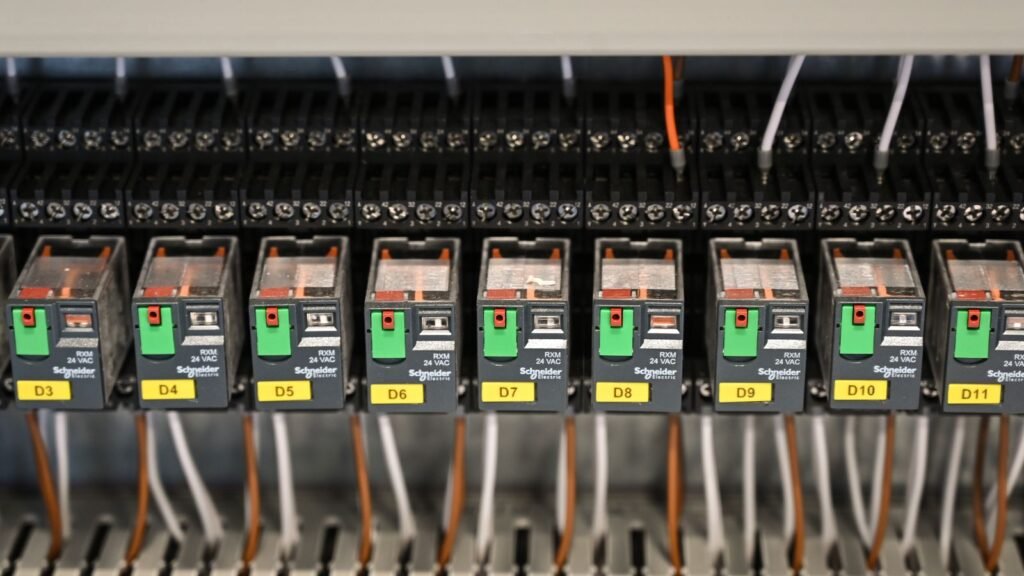
Featured image: industrial electrical relay panel, Vladimir Srajber / Pexels, used under the Pexels licence. Illustrative photograph; not a Titania/PyXis product image or the Modbus test reported here. No other company’s product performance is asserted.